


Hello, I’m Clive Chen, an engineer here at Rapmaf. My team and I spend our days working with clients from the US, Europe, and all over the world, helping turn their designs into real, functional parts. A huge part of that work involves plastics. I often find that while a designer or procurement manager knows exactly what they want the final part to do, there can be a gap in understanding the best way to make it. That gap can lead to designs that are more expensive than they need to be, difficult to manufacture, or don’t perform as expected.
My goal here is to bridge that gap. This isn’t a theoretical, academic paper. It’s a practical, on-the-ground look at the primary plastic manufacturing processes, written from one engineer to another. We’ll explore how these processes work, where they excel, what their limitations are, and—most importantly—how you can design and specify your parts to get the best possible outcome. We’ll start by tracing plastic back to its source and then dive deep into the two most dominant manufacturing methods you’ll likely encounter: Injection Molding and Extrusion.
First, Where Does Plastic Actually Come From?
Before we can shape a plastic part, we need the raw material itself. Understanding its origin is crucial because it dictates the foundational properties we have to work with. While there are emerging bio-plastics, the overwhelming majority of industrial polymers you’ll specify on a print still begin their life as crude oil or natural gas.
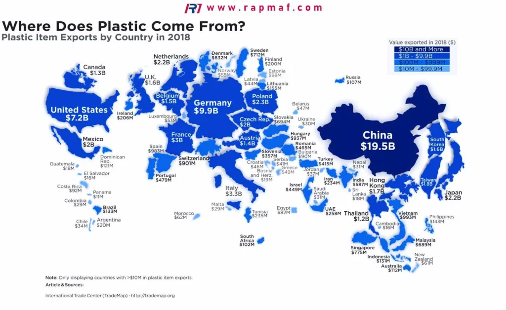
The journey from a barrel of oil to a bag of plastic pellets is a marvel of industrial chemistry, but for our purposes as engineers specifying parts, the simplified flow chart looks like this:
- Refining: Crude oil is heated in a fractional distillation tower. Lighter components rise, and heavier ones stay at the bottom. A key fraction called Naphtha is extracted, which is the primary feedstock for the plastics industry.
- Cracking: The long hydrocarbon molecules in Naphtha are “cracked” (broken apart) using high heat and pressure into smaller, more useful molecules called monomers. The most common ones are ethylene and propylene.
- Polymerization: This is the magic step. Under the influence of catalysts, these small monomer molecules are linked together into incredibly long, repeating chains called polymers. “Poly” literally means “many.” So, many ethylene monomers link up to become poly-ethylene (PE), and many propylene monomers become poly-propylene (PP).
- Compounding & Pelletizing: The resulting raw polymer resin is then often mixed with additives—colorants, UV stabilizers, flame retardants, reinforcing fibers (like glass or carbon), etc.—to achieve the specific properties required for an application. Finally, this compounded material is extruded into spaghetti-like strands, cooled, and chopped into the small, uniform pellets that arrive at a facility like ours.
So, when you specify “Polycarbonate (PC)” or “Acetal (POM)” on a drawing, you are calling for a specific type of these long-chain molecules, delivered in pellet form, ready for manufacturing.
The Workhorses of Production
Once we have the raw material, the real work of creating your part begins. There are many ways to form plastic, but your project will most likely involve one of the following. Let’s start with the undisputed king of high-volume production.
Injection Molding: The Go-To for Complex, Repeatable Parts
If you need thousands, or millions, of identical plastic parts with complex geometries, injection molding is almost always the answer. The process is conceptually simple but devilishly complex in its execution. Think of it as a highly sophisticated, automated hot glue gun.

The Process, Step-by-Step:
- Clamping: A precision-machined steel or aluminum mold, which is the negative of your part, is clamped shut under immense force. Molds are typically two-halved (a “core” and a “cavity” side).
- Injection: Plastic pellets are fed from a hopper into a heated barrel containing a reciprocating screw. The screw melts and mixes the plastic, then acts like a plunger, injecting the molten material (“shot”) at high pressure into the empty mold cavity.
- Dwelling & Cooling: The pressure is maintained for a short period (dwelling) to ensure the cavity is fully packed. The part then cools and solidifies, taking the shape of the mold. This is often the longest part of the cycle.
- Ejection: The mold opens, and an ejector pin system pushes the finished part out. The cycle then immediately repeats.
When to Choose Injection Molding:
- High Volumes: The upfront cost of the mold (tooling) is significant, ranging from a few thousand to tens of thousands of dollars or more. This cost is amortized over the production run, so the per-part price becomes very low at high volumes (typically 10,000+ units).
- Complex Geometry: It excels at creating parts with intricate features like ribs, bosses, snaps, and complex curvatures.
- Tight Tolerances: With a well-designed part and a high-quality mold, very consistent and tight tolerances can be held. Here at Rapmaf, for robustly designed parts made from stable materials like POM or PEEK, holding tolerances in the ±0.01 mm to ±0.05 mm (±0.0004″ to ±0.002″) range is a common requirement we can achieve, though this is highly dependent on part geometry and material.
- Excellent Surface Finish: The finish of the mold surface is directly transferred to the part, allowing for anything from a high-gloss, mirror finish to a textured one.
Design for Manufacturability (DFM) is Non-Negotiable:
This is the single most critical factor for a successful injection molded part.
- Uniform Wall Thickness: This is rule #1. Varying thicknesses cause the part to cool at different rates, leading to warpage, sink marks, and internal stresses.
- Draft Angles: Part surfaces parallel to the mold opening direction must have a slight taper (typically 1-3 degrees) so the part can be ejected without being damaged or getting stuck.
- Radii and Fillets: Sharp internal corners create stress concentrations. Adding a small radius strengthens the part and improves plastic flow in the mold.
- Gate Location: The point where plastic enters the mold cavity is critical. A poorly placed gate can cause cosmetic flaws or structural weaknesses.
Case Study: Manufacturing a PEEK Gear for a Medical Pump
A client needed a small, 15 mm (0.59″) diameter gear for a peristaltic pump. The requirements were extreme: it had to withstand repeated steam sterilization (autoclaving at 134°C / 273°F), be biocompatible, and maintain dimensional stability to ±0.015 mm on the tooth profile for consistent pump performance.
The client’s initial plan was to CNC machine the gear from PEEK rod stock. This was perfectly feasible for their 50-piece prototype run. However, when they needed to scale up to 20,000 units, the per-part cost of machining became prohibitive. We proposed transitioning to injection molding.
Our engineering team worked with them to adapt the design for molding. We added a minuscule draft angle (0.5 degrees) to the gear faces and carefully designed a “pin gate” in the center to ensure uniform radial flow into the gear teeth, which was critical for tolerance control. We selected a high-flow, medical-grade PEEK. The mold was built from hardened H-13 tool steel with a specialized high-temperature control system to manage PEEK’s high melt temperature (~380°C / 716°F).
The result? The molded PEEK gears met all dimensional and performance requirements at a fraction of the per-part cost of machining. We provided a full First Article Inspection (FAI) report to validate the process, and now run this part for them in batches of 10,000. This project is a perfect example of that crucial decision point between machining and molding based on volume.
To help with that very decision, here is a comparison table that we often use to guide our clients.
Table 1: Injection Molding vs. CNC Machining for Plastic Parts
| Feature | Injection Molding | CNC Machining | Best Choice For… |
|---|---|---|---|
| Unit Cost (High Volume) | Very Low ($) | High ($$$) | Molding: Cost-sensitive mass production. |
| Upfront Cost (Tooling) | High ($$$$) | Very Low / None ($) | Machining: Prototypes, low-volume runs. |
| Lead Time (First Parts) | Weeks to Months (for tool) | Hours to Days | Machining: Speed and rapid prototyping. |
| Geometric Complexity | High (but with DFM rules) | Very High (fewer constraints) | Machining: Extremely complex or “impossible to mold” geometries. |
| Material Waste | Low (runners can be reground) | High (material is cut away) | Molding: Material efficiency. |
| Tolerances | Good to Excellent (±0.01-0.1mm) | Excellent to Superior (±0.005-0.05mm) | Machining: When ultimate precision is the top priority. |
| Maximum Part Size | Limited by machine/mold size | Limited by machine travel | Depends on the specific part, but both can make very large parts. |
2. Extrusion: For Continuous, Uniform Profiles
While injection molding creates discrete parts, extrusion creates continuous lengths of a uniform cross-section. If you can draw a 2D shape and imagine pulling it into a 3D length, it can likely be extruded.
The Process, Step-by-Step:
It’s very similar to the start of the injection molding process, but it never stops.
- Melting & Conveying: Plastic pellets are fed into a heated barrel with a rotating screw. The screw melts, mixes, and pressurizes the plastic, forcing it continuously forward.
- Forcing Through a Die: Instead of injecting into a mold, the molten plastic is forced through a shaped die. The die is a steel plate with a hole cut in the exact cross-sectional shape of the desired profile.
- Cooling & Sizing: The emerging profile is pulled through a cooling bath (usually water) or cooled by air. Sizing plates or rollers may be used to ensure the final dimensions are accurate as it cools.
- Pulling & Cutting: A puller (like a belt or wheel system) draws the profile along at a constant speed. At the end of the line, it is cut to the desired length by a saw or shear.
When to Choose Extrusion:
- Constant Cross-Section Parts: This is the defining characteristic. Think pipes, tubes, window frames, gaskets, door seals, and plastic lumber.
- Very Long Parts: The process is continuous, so part length is limited only by shipping and handling constraints.
- Low Tooling Cost: A die is much simpler and cheaper to make than an injection mold.
- High Production Speed: Extrusion lines can run very fast, producing thousands of feet or meters of product per hour.
Case Study: Prototyping a Custom TPE Gasket
An industrial equipment manufacturer needed a custom gasket to seal an access panel. The cross-section was a complex “P” shape, and the material needed to be flexible, UV resistant, and have excellent compression set. They needed 100 meters (approx. 328 ft) for prototyping before committing to a large-scale order.
Given the part’s uniform profile and required length, extrusion was the only viable option. Injection molding was impossible, and machining it would be astronomically expensive and wasteful.
We worked with their 2D CAD file of the profile to design and CNC wire-EDM the extrusion die. The material selected was a thermoplastic elastomer (TPE), which offers rubber-like properties but can be processed like a standard thermoplastic. We ran a short setup batch to dial in the puller speed and cooling bath temperature, which are critical for preventing the complex profile from distorting as it cools.
Within about 7 business days, the client had the 100 meters of their custom gasket for fit and function testing on their prototype units. The low cost of the die made this rapid prototyping highly affordable. Once they approved the design, scaling up to a production run of 5,000 meters was a simple matter of scheduling time on the extrusion line.
Blow Molding: For Everything Hollow
If you’ve ever held a plastic bottle, you’ve held a blow-molded part. This process is the undisputed champion for producing hollow, thin-walled parts quickly and cheaply. Think of it as industrial-scale glass blowing, but with plastic.

The Process, Step-by-Step:
There are a couple of variations, but the most common is Extrusion Blow Molding:
- Extrude a Parison: The process starts like extrusion, but instead of a solid profile, a hollow tube of molten plastic, called a parison, is extruded downwards.
- Capture in a Mold: A two-part mold closes around the parison, pinching one end shut.
- Inflate: Compressed air is injected into the parison (usually through a pin in the top), inflating it like a balloon. The plastic stretches outwards and presses against the cold walls of the mold cavity.
- Cool & Eject: The plastic solidifies in the shape of the mold. The mold opens, the part is ejected, and any excess material (called “flash”) is trimmed off.
When to Choose Blow Molding:
- Hollow Parts: This is its sole purpose. Bottles, containers, fuel tanks, watering cans, automotive ducting.
- High Volume, Low Cost: Like injection molding, tooling can be expensive, but the cycle times are very fast, leading to an extremely low per-part cost in mass production.
- Double-Walled Parts: It can also be used to create items like carrying cases or coolers that have two walls with air trapped in between.
Design Considerations: A key factor is that the wall thickness isn’t perfectly uniform; it will be thinner in areas that have to stretch more, like corners. Designing with generous radii and avoiding sharp, deep features is crucial.
Thermoforming (or Vacuum Forming): Shaping Plastic Sheets
Thermoforming is a beautifully simple and cost-effective process for parts that are essentially shells or trays. Unlike the other methods that start with raw pellets, thermoforming starts with a pre-extruded sheet of plastic.
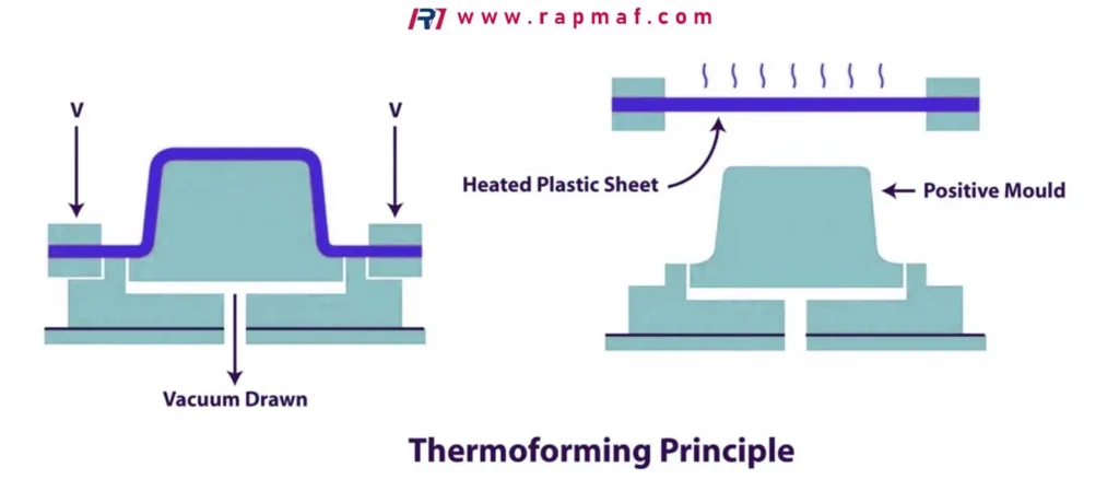
The Process, Step-by-Step:
- Clamp & Heat: A sheet of plastic is clamped into a frame and heated by an overhead element until it becomes soft and pliable (like a sheet of cooked lasagna).
- Drape & Form: The soft sheet is lowered over or into a mold.
- Apply Vacuum/Pressure: A vacuum is pulled through small holes in the mold, sucking the sheet down so it conforms tightly to the mold’s surface. Sometimes, air pressure from above is also used to help.
- Cool & Trim: The plastic cools and hardens in its new shape. The formed part is then removed from the sheet, and the excess material is trimmed away.
When to Choose Thermoforming:
- Packaging: Think blister packs, clamshells, and food trays. This is its biggest market.
- Large, Simple Shells: It’s also great for things like equipment enclosures, vehicle door panels, and refrigerator liners.
- Low Tooling Cost & Fast Turnaround: The molds are typically single-sided and made of aluminum, which is much cheaper and faster to produce than a hardened steel injection mold. This makes it ideal for prototypes and lower-volume production runs.
Design Considerations: The process inherently involves stretching material, so you must design for it. Deep pockets or sharp corners will result in significant thinning. A good rule of thumb is that the depth of a feature should not exceed its width.
Choosing the Right Plastic: A Practical Framework
Selecting the right material is just as important as selecting the right process. A beautiful design made from the wrong plastic will fail. Here at Rapmaf, we work with a wide range of engineering-grade thermoplastics, including high-performance materials like PEEK and workhorses like POM (Acetal). The choice always comes down to a balance of performance, processability, and price.
Here’s the thought process I go through with clients:
- What is the Mechanical Load? Will the part be under tension, compression, or impact? This will guide you toward materials with the right tensile strength, flexural modulus, and impact resistance (Izod). For example, a snap-fit clip needs a flexible material like Polypropylene (PP), while a structural housing might require a rigid, glass-filled Nylon or Polycarbonate (PC).
- What is the Operating Environment?
- Temperature: What is the maximum continuous service temperature? This will immediately narrow your choices. A part near an engine needs a high-temp material like PEEK, while a consumer product housing is fine with ABS.
- Chemicals: Will the part be exposed to oils, solvents, acids, or cleaning agents? Materials like POM and PEEK have excellent chemical resistance, whereas others like PC can be attacked by certain chemicals.
- UV Exposure: If the part is used outdoors, you need a UV-stabilized grade of material (e.g., ASA or specific grades of PP) to prevent it from becoming brittle and discolored.
- Are There Any Regulatory Requirements? For medical devices, you need biocompatible materials (like medical-grade PEEK or PC). For food contact, you need FDA-compliant grades (many grades of PP, PE, and POM are available). For electronics, you might need a flame-retardant rating (e.g., UL94 V-0).
- What is the Budget? Cost varies dramatically. Commodity plastics like PP and PE are very inexpensive. Engineering plastics like ABS, PC, and POM are in the mid-range. High-performance polymers like PEEK can be 50-100 times more expensive than PP. Always start with the lowest-cost material that meets all your non-negotiable performance requirements.
How to Write an RFQ That Gets You Accurate Quotes, Fast
As a manufacturer, the quality of the Request for Quotation (RFQ) we receive directly impacts the quality and speed of the quote we can provide. A complete RFQ prevents back-and-forth emails and ensures we’re quoting exactly what you need. When we prepare a project for a client, we often provide documents like a Certificate of Conformance (CoC) or a First Article Inspection (FAI) report, but it all starts with a clear RFQ.
Here’s a checklist you can use. If you provide this information, any good supplier will be able to give you a sharp, accurate quote.
Table 2: The Engineer’s RFQ Checklist for Plastic Parts
| RFQ Item | What to Include & Why It’s Important |
|---|---|
| 1. 3D CAD Files | Format: STEP is the universal standard. Why: This is essential for calculating part volume, analyzing geometry for manufacturability (DFM), and programming toolpaths. |
| 2. 2D Engineering Drawings | Format: PDF. Why: This is where you define everything the 3D model can’t show: critical tolerances, surface finish callouts (e.g., SPI-A2, MT-11010), material specifications, and any specific notes or inspection requirements. |
| 3. Material Specification | Be specific. “Plastic” is not enough. Example: “Acetal Copolymer (POM-C), Natural. DuPont Delrin 150 or equivalent.” Why: This is the biggest driver of part cost and performance. Listing an “or equivalent” gives your supplier flexibility to source a comparable material, which can sometimes improve cost and lead time. |
| 4. Quantities | List specific volumes. For example: “Pricing for 1,000, 5,000, and 20,000 units.” Also include Estimated Annual Usage (EAU) if applicable. Why: Manufacturing processes are volume-dependent. The quote for 100 machined parts will be completely different from 100,000 molded parts. |
| 5. Color & Finish | Specify the color (e.g., Pantone number, RAL number, or “Natural”) and the required surface finish. Why: Colorants are additives that affect cost. The surface finish dictates how the mold is polished or textured, which significantly impacts tooling cost. |
| 6. Required Documentation | State your quality requirements upfront. Do you need a Material Certificate? A Certificate of Conformance (CoC)? First Article Inspection (FAI) report? Statistical Process Control (SPC) data? Why: These documents require time and resources to prepare, and this needs to be factored into the quote. |
| 7. Target Lead Time | What is your project timeline? “ASAP” is not helpful. Example: “Prototypes required in 3 weeks, first production run in 8 weeks.” Why: This helps us determine if we can meet your schedule or if expediting is needed. For prototypes and small batches, we can often deliver in a 3–7 day timeframe, but mass production tooling takes longer. |
Frequently Asked Questions (FAQs)
I get asked these questions a lot, so I thought I’d answer them directly here.
What are the 5 types of manufacturing processes?
While there are dozens, the five most common types you’ll encounter for plastics are:
- Injection Molding: For complex, solid parts in high volumes.
- Extrusion: For continuous profiles with a uniform cross-section (pipes, tubing).
- Blow Molding: For hollow parts like bottles and tanks.
- Thermoforming: For shaping plastic sheets into packaging and trays.
- Rotational Molding: For very large, seamless hollow parts (e.g., large tanks, kayaks).
Is plastic made from oil, yes or no?
Yes. The vast majority (over 99%) of the plastics we use in industrial and consumer applications today are derived from fossil fuels, primarily crude oil and natural gas.
Why does vinegar turn milk into plastic?
This is a great home science experiment! You are creating what’s called casein plastic. Milk contains a protein called casein. The acid in the vinegar causes the casein molecules to unfold and link together (a process called denaturation), separating from the liquid whey. When you dry the resulting solid, it becomes a hard, biodegradable material. It was one of the very first plastics, used for things like buttons and jewelry before the invention of petroleum-based polymers, but it is chemically completely different from modern industrial plastics like Polycarbonate or ABS.
What is the process of manufacturing plastic?
In short, it’s a two-stage journey. Stage 1: Polymer Creation. Crude oil is refined and “cracked” into basic chemical building blocks (monomers). These monomers are then chemically linked into long chains (polymers) to create raw plastic resin, which is formed into pellets. Stage 2: Part Formation. These pellets are melted and formed into the final part shape using a manufacturing process like injection molding, extrusion, or one of the others we’ve discussed.
Final Thoughts
Navigating the world of plastic manufacturing can seem complex, but it really boils down to matching your part’s geometry, volume, and performance requirements to the right process and material. My hope is that this guide has given you a solid framework for making those decisions and for communicating your needs clearly.
The best results always come from collaboration. Think of your manufacturing partner not just as a supplier, but as an extension of your engineering team. If you have a design and you’re not sure about the best way to make it, just ask.
References
- ASM International, Engineered Materials Handbook, Volume 2: Engineering Plastics. A comprehensive resource on plastic materials and their properties. Link to ASM International
- ISO 294-1:2017, Plastics — Injection moulding of test specimens of thermoplastic materials. The international standard governing injection molding test procedures, providing insight into process control. Link to ISO Standard